by Rémy Fehlmann

1 
2 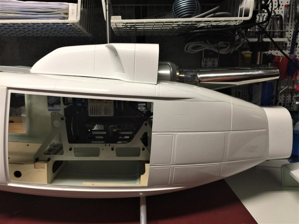
3 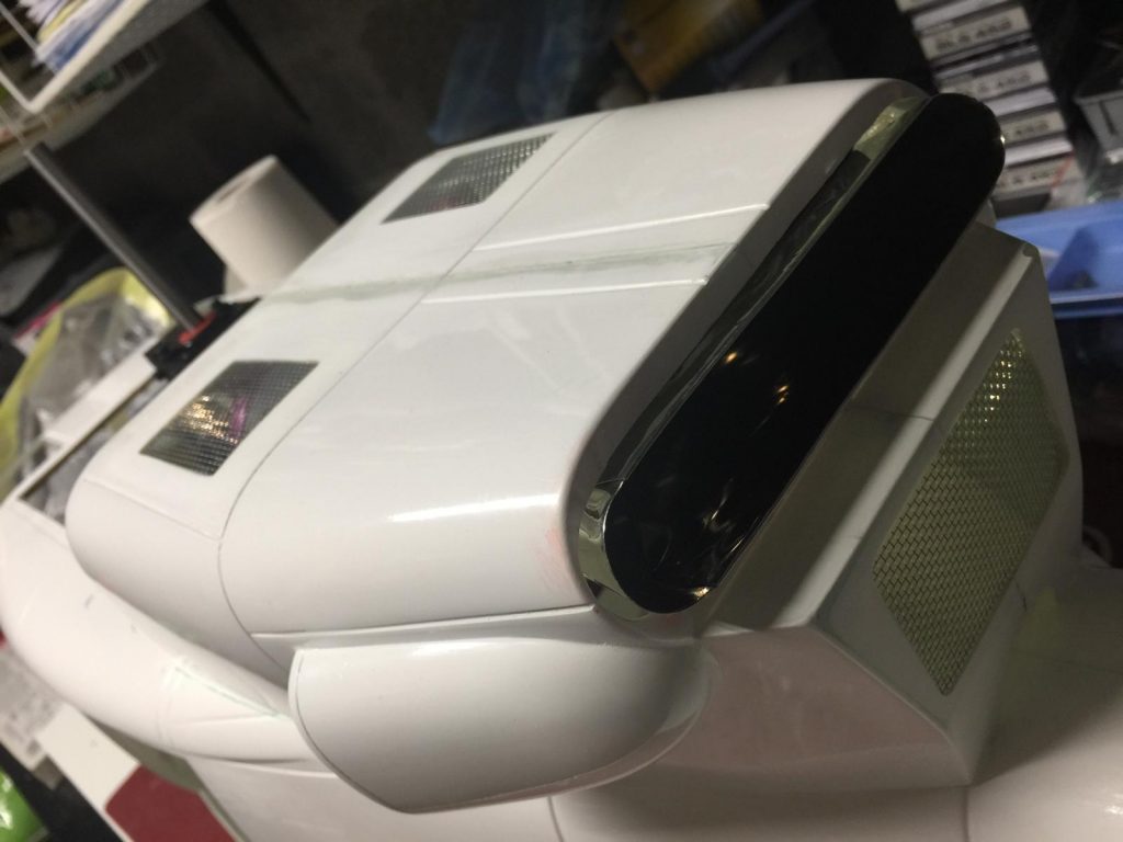
4 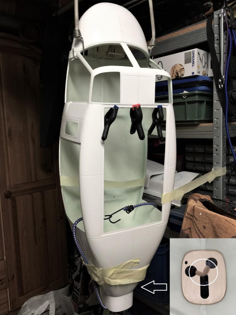
5 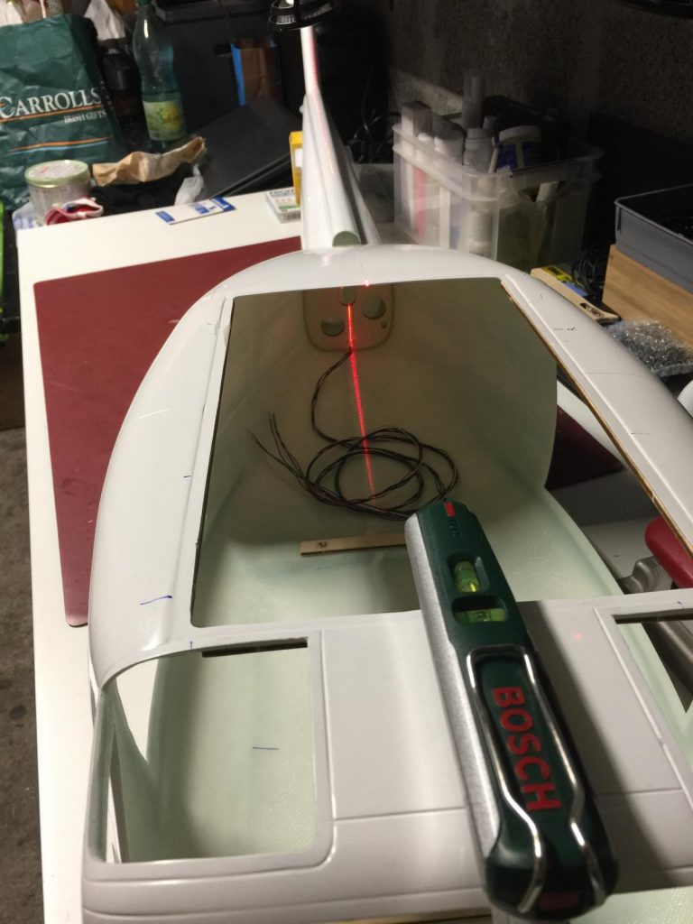
6 
7 
8 
9 
10 
11 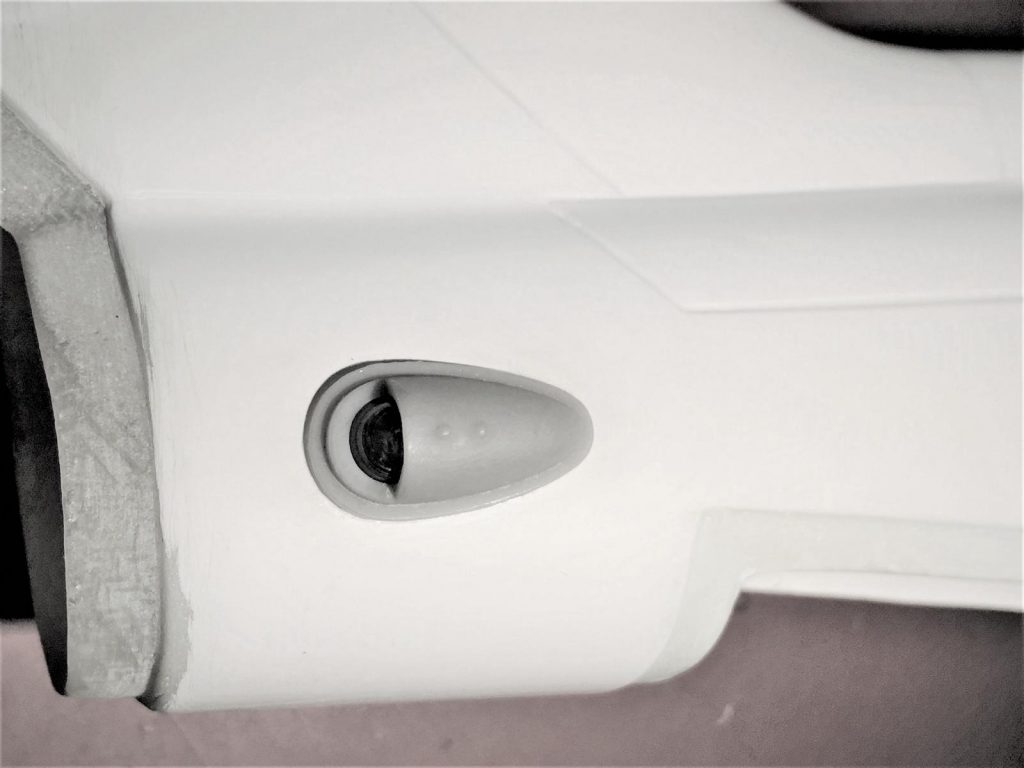
12 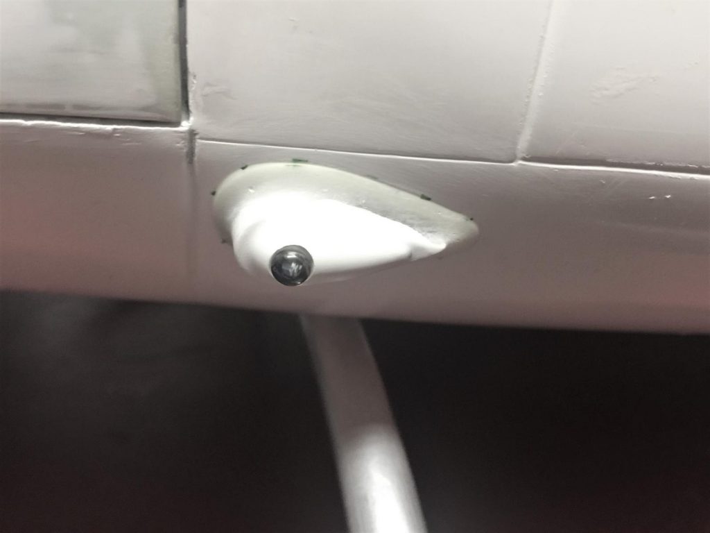
13 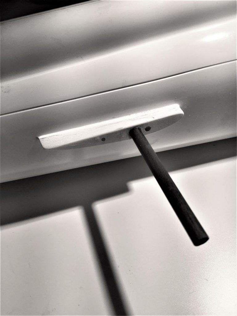
14 
15 
16 
17 
18 
19 
20 
21 
222 
23 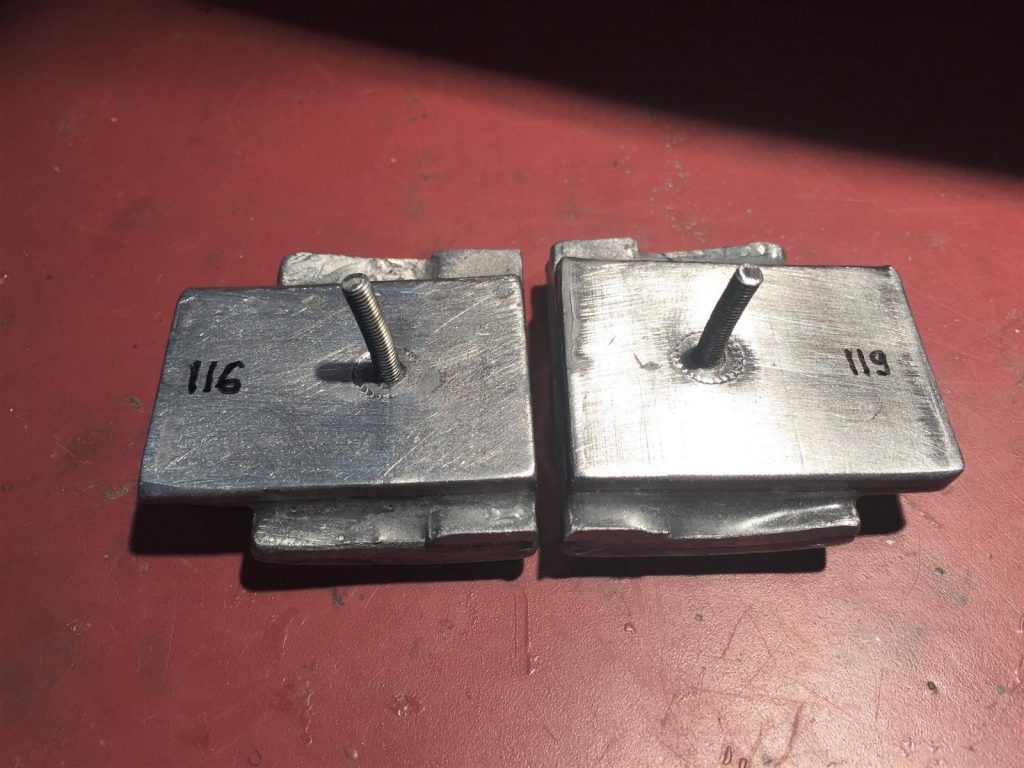
24 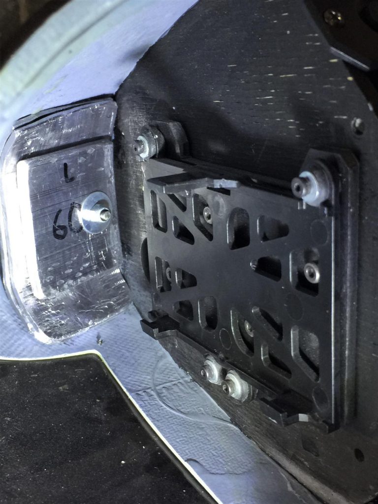
25 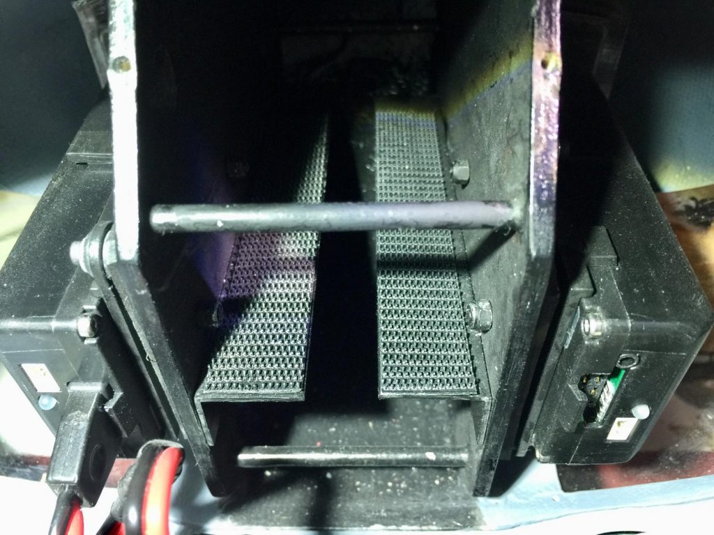
26 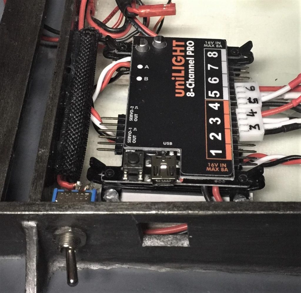
27 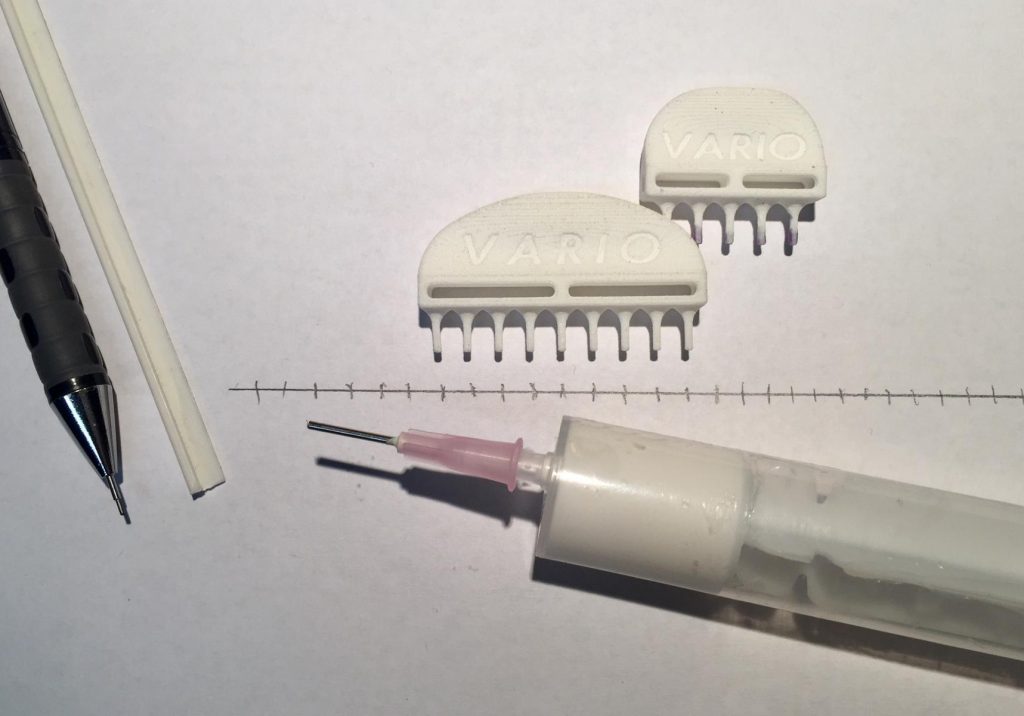
28 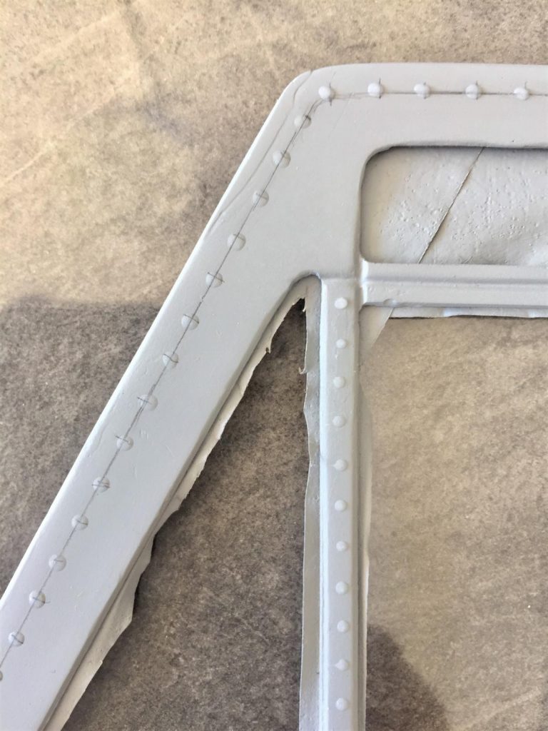
29 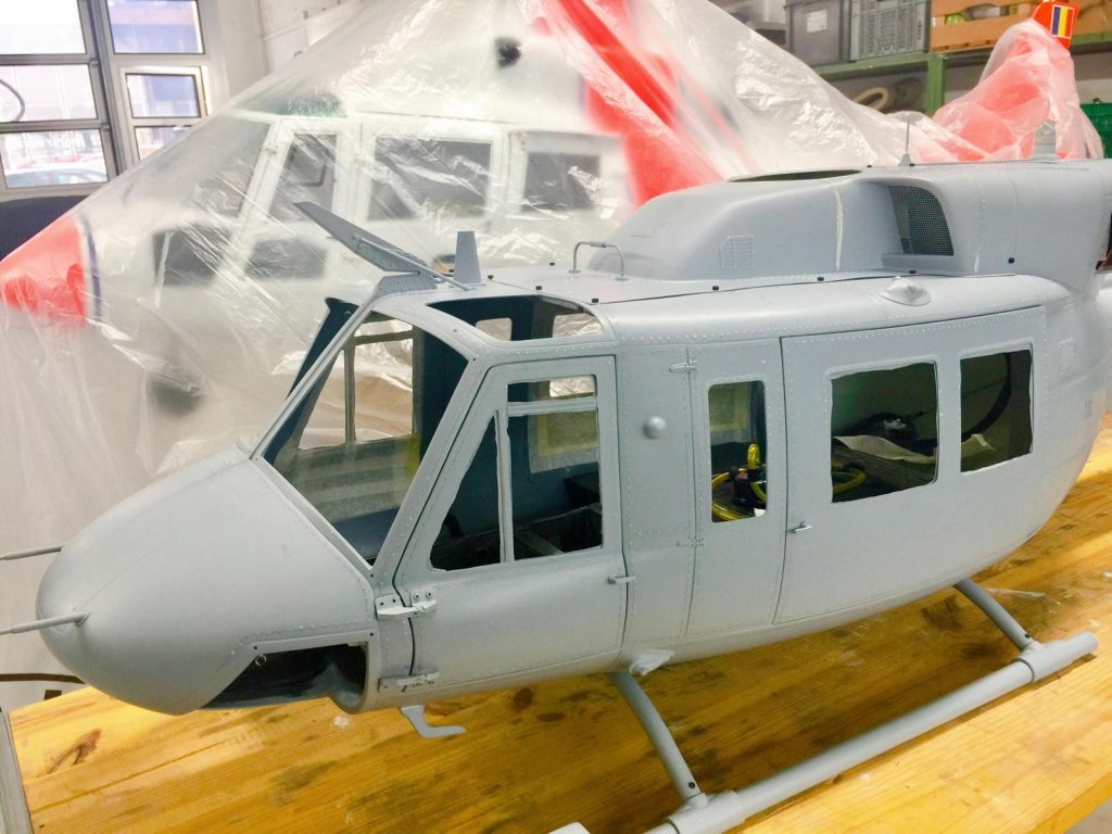
30 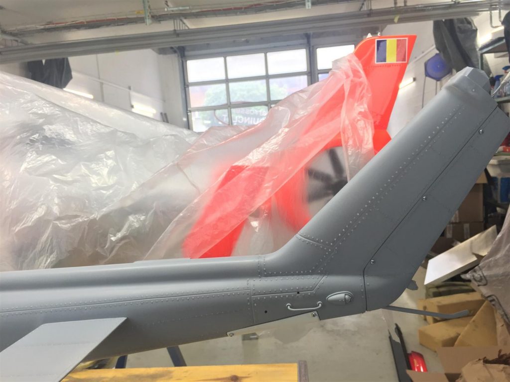
31 
32 
33 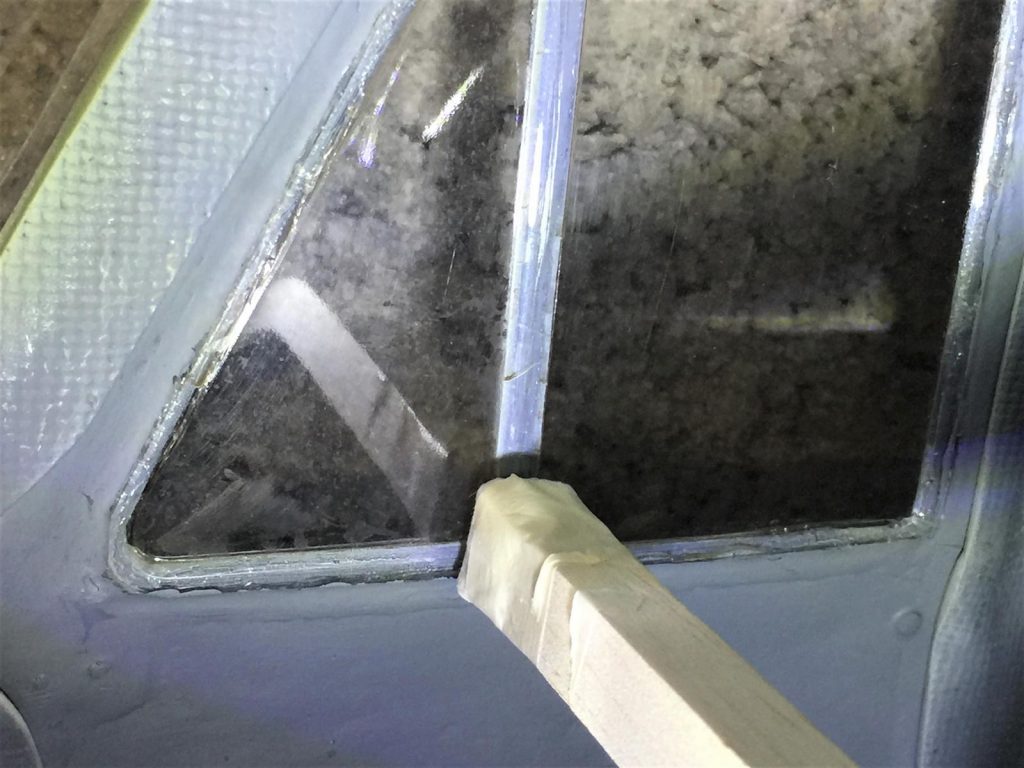
34 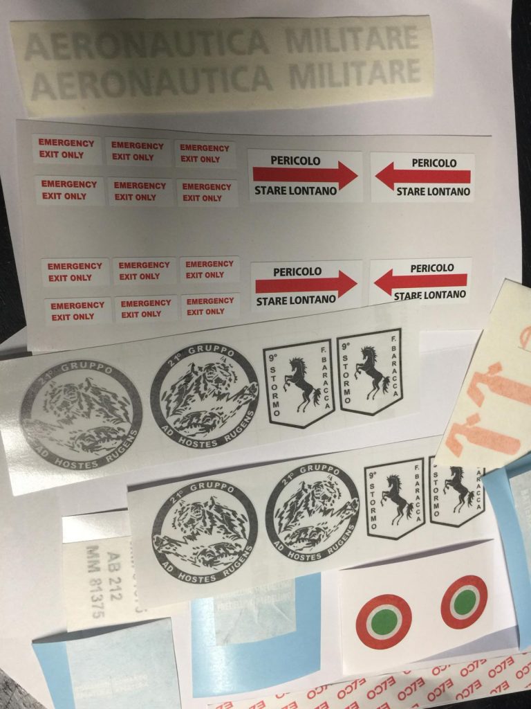
35 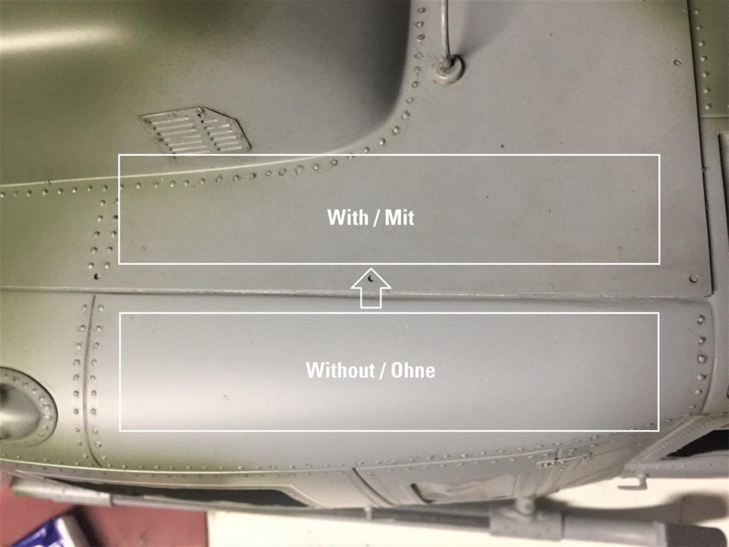
36 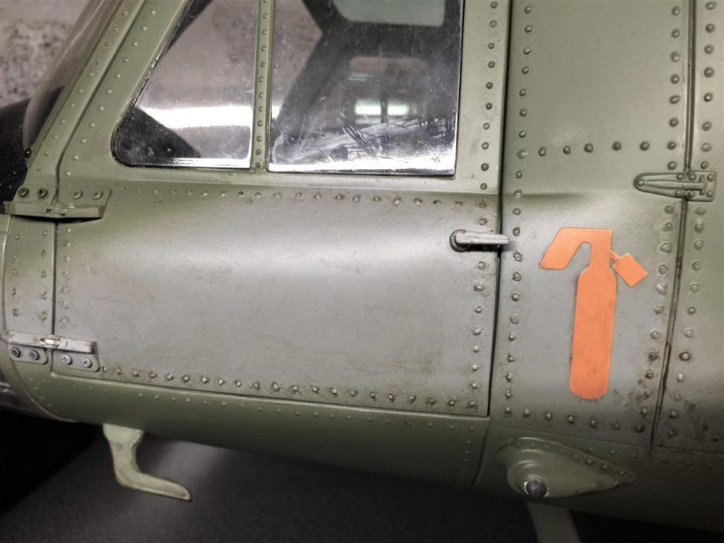
37 
38 
39 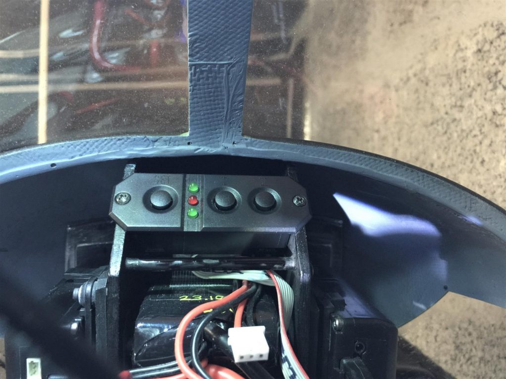
40 
41 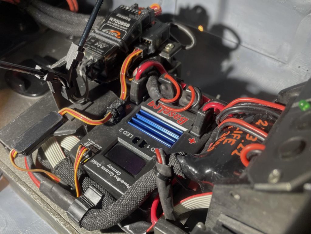
42 
43 
44 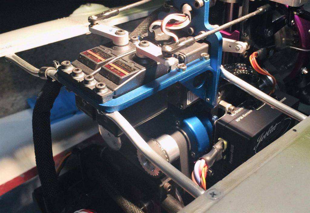
45 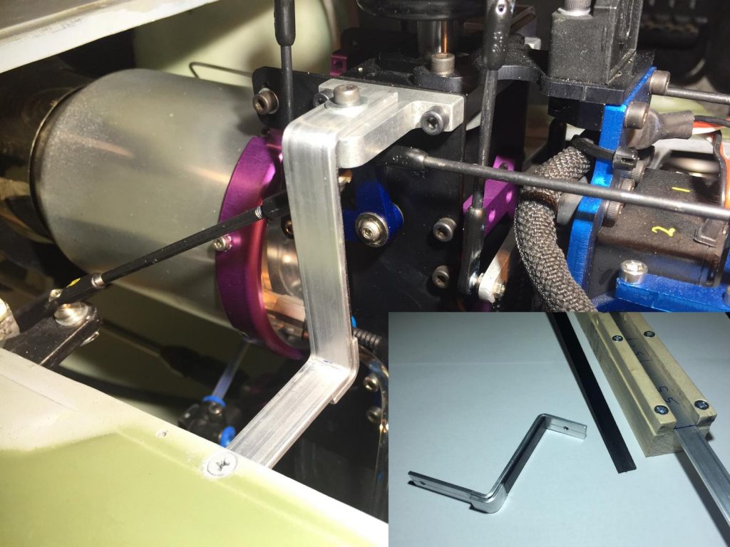
46 
47 
48 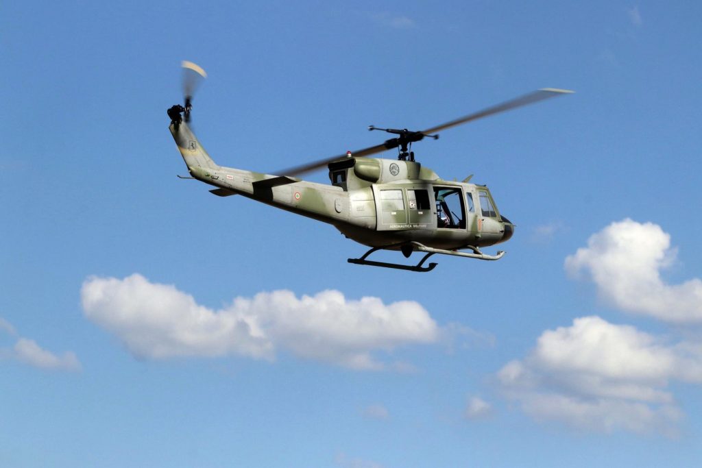
49 
50


- Preparation for cutting
Decoration strips for cars work very well to mark the openings cut with the Dremel. Once the openings are cut, sand by hand till reaching the strip.
. - Front Woodwork
It is recommended to customize and paint in advance, before gluing the woodwork as access is more difficult afterwards.
. - Mechanic Check
The positioning of the mechanics and its angle are important. Place it as forward as possible to avoid having to add lead in the front. Make sure that the engine hood isn’t stuck with the two servos located at the top of the turbine.
. - Exhaust Check
Check that the exhaust outlet of the turbine coincides with its opening in the fuselage.
. - Torque Tube Support
The gluing of this piece is easier with some elastics attached from the back.
. - Tail Alignment
The alignment of the tail can be done with a laser. Caution with the positioning of the tail gearbox support (Ord.No. 870/3); it does impact the vertical and horizontal position of the tail blades.
. - Homemade Tool
Just a homemade tool to help glueing, made with a few pieces from a DIY store.
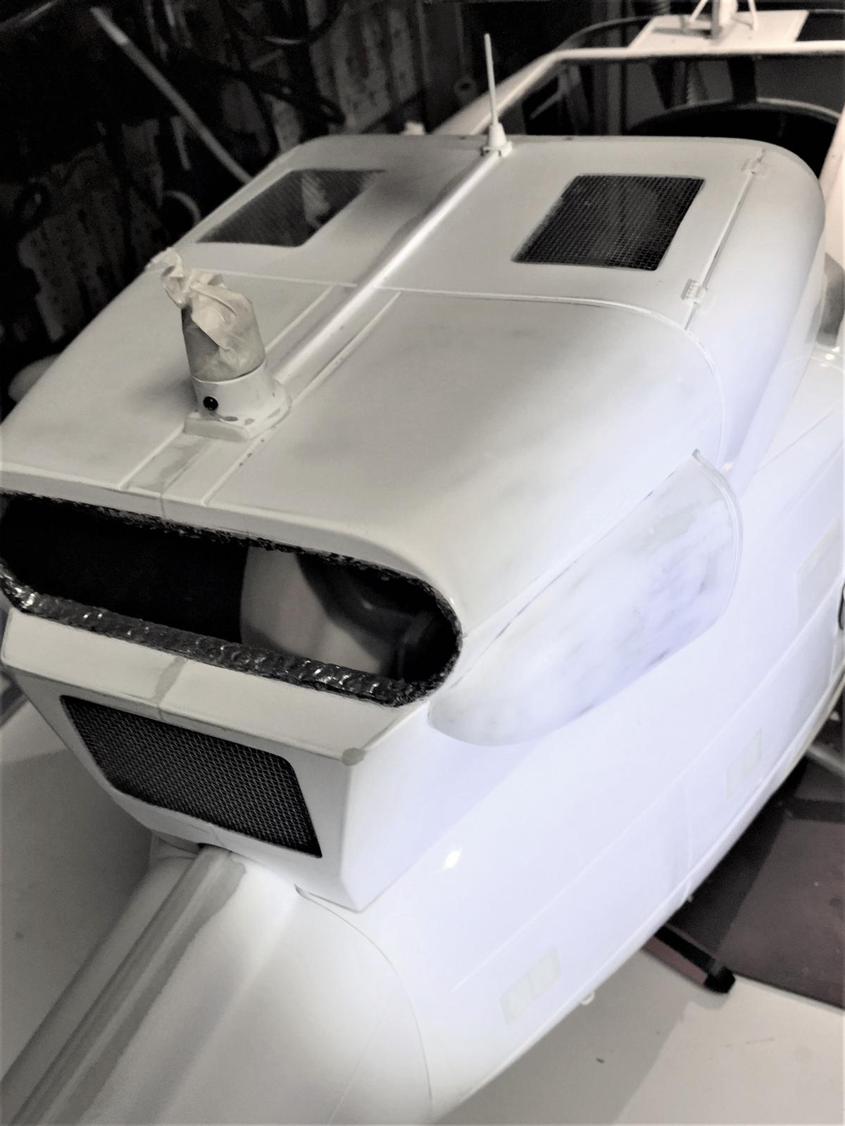
. - Sanding and Accessories
Sanding and installing scale accessories. The base of the rotating light has been shortened to the maximum and it’s base insulated with same material as inside the dog house.
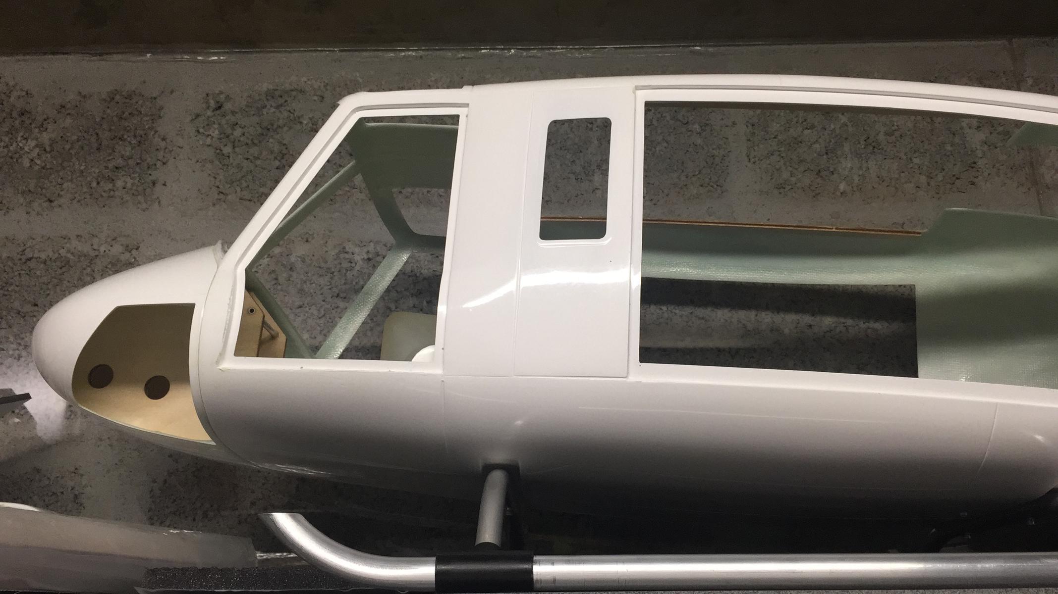
. - Scale Details
Adding more scale details and holes to fix the windows.
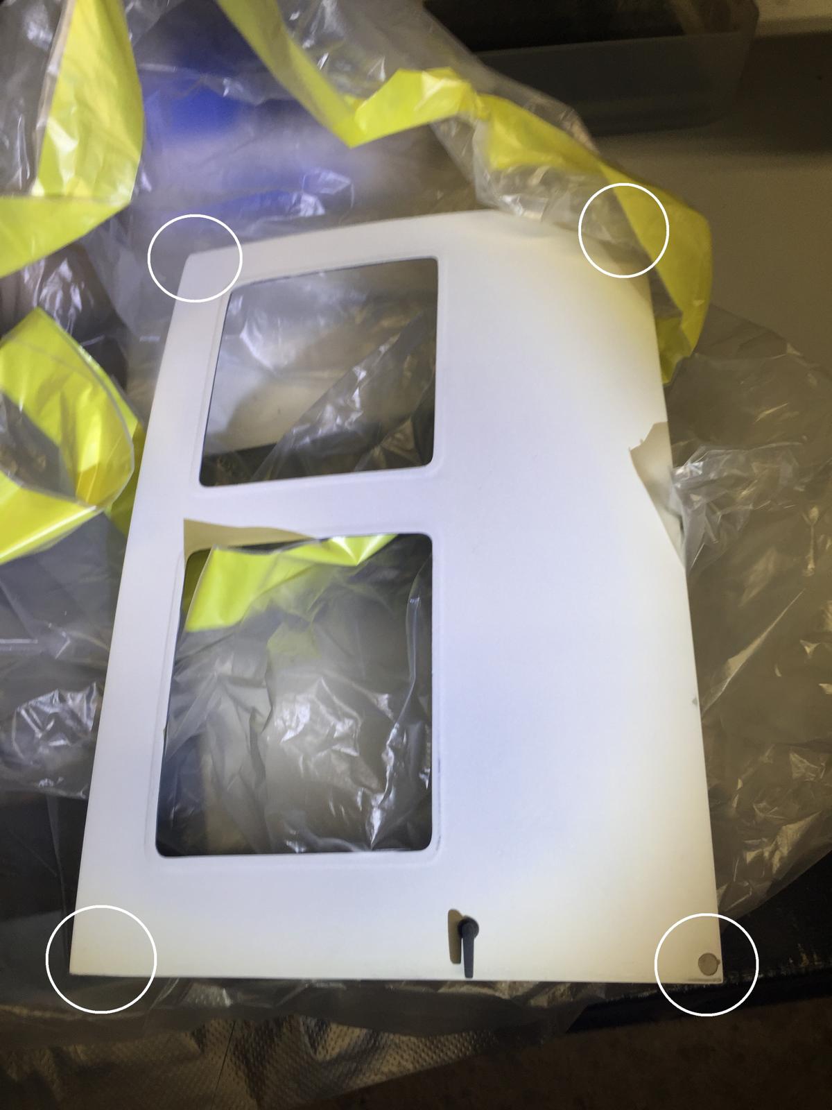
. - Hidden Magnets
Here doors can be either in closed position (magnets) or open (two screws per door with Nylstop). Magnets are hidden inside the doors and located in the corners.
. - Side Nav Lights
Preparation of the supports for high intensity leds. Leds are also sanded with very fine abrasive so that the light is scattered over a wider radius.
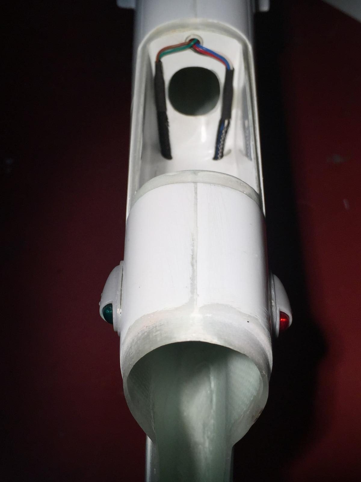
. - Rear Nav Lights
Lighting wires are inside a little plastic tube glued inside the tail with just a few drops of strong glue.
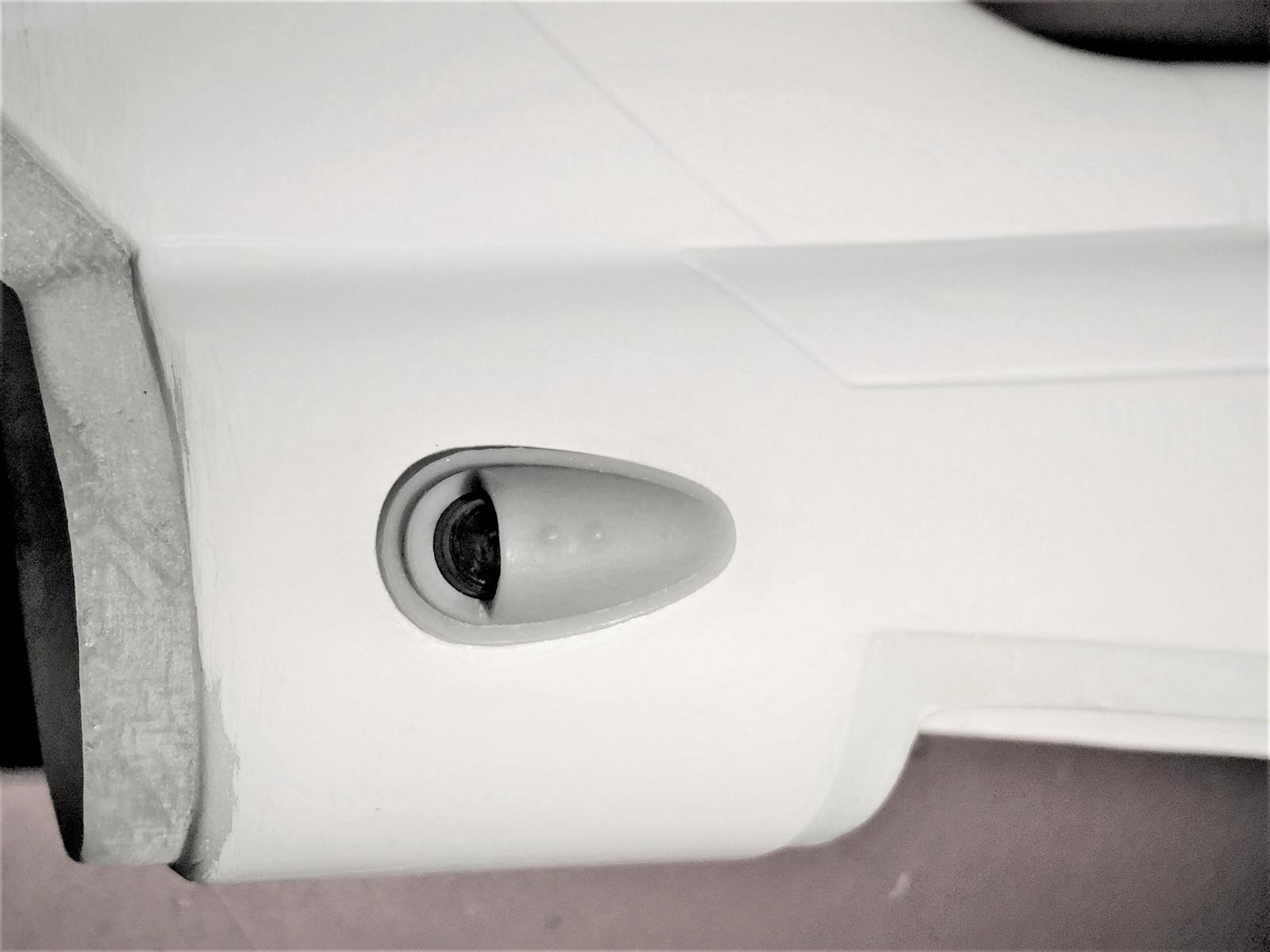
. - Front Nav Lights
This piece must be sanded well until it gets the right shape.
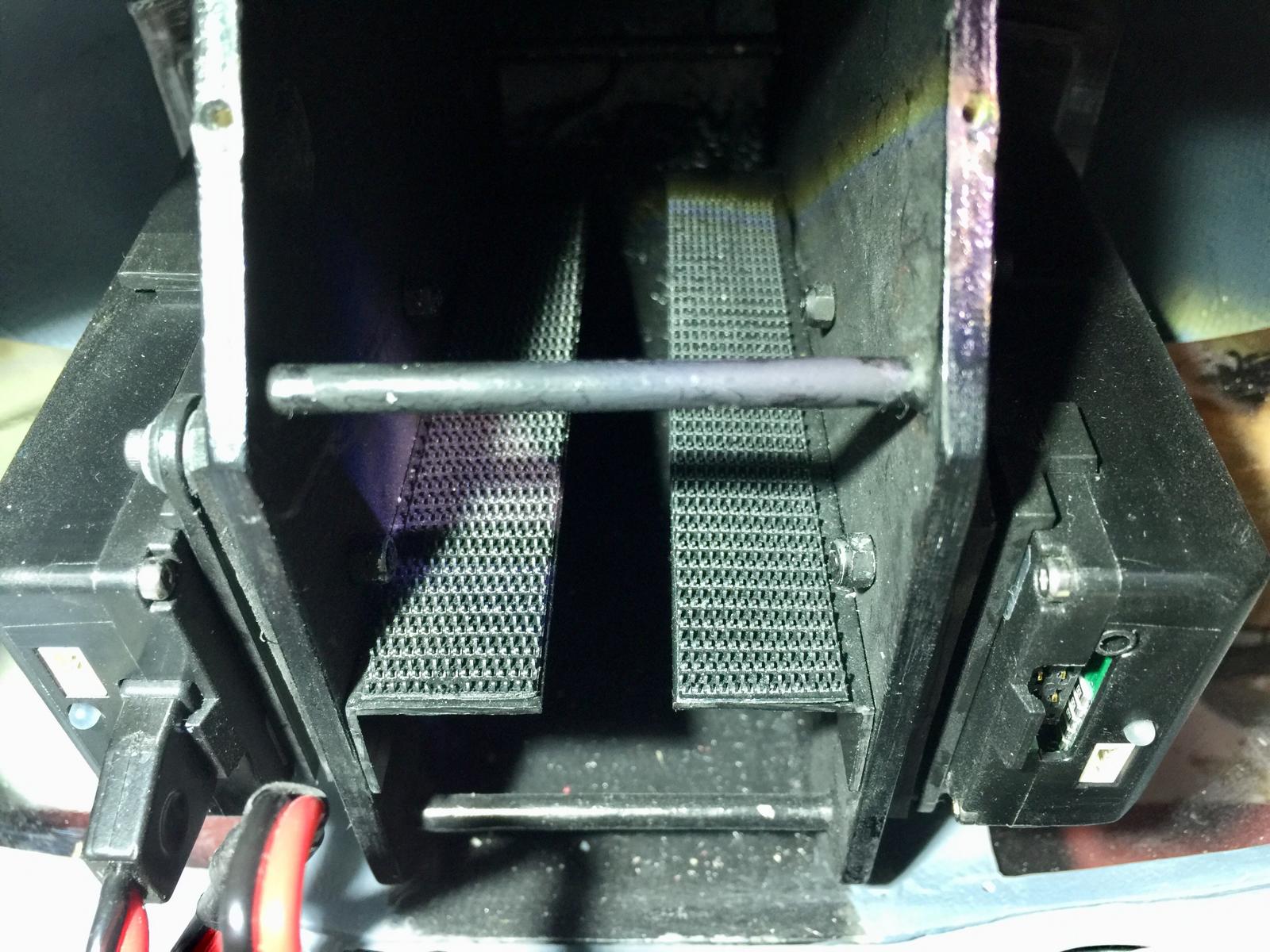
. - Carbon Rod for Stab
Addition of a carbon rod to prevent any vibration of the Stab. There is two rods as a single one crossing would prevent the torque tube from passing.
. - Rod Plug for Stab
Bonding of a rigid plastic tube receiving the carbon rod.
. - Tank Setup
There are different ways to setup, with or without header tank. Pay attention to the airtightness of the red cap, do pressure tests and rinse the tank thoroughly to remove any unwanted particles.
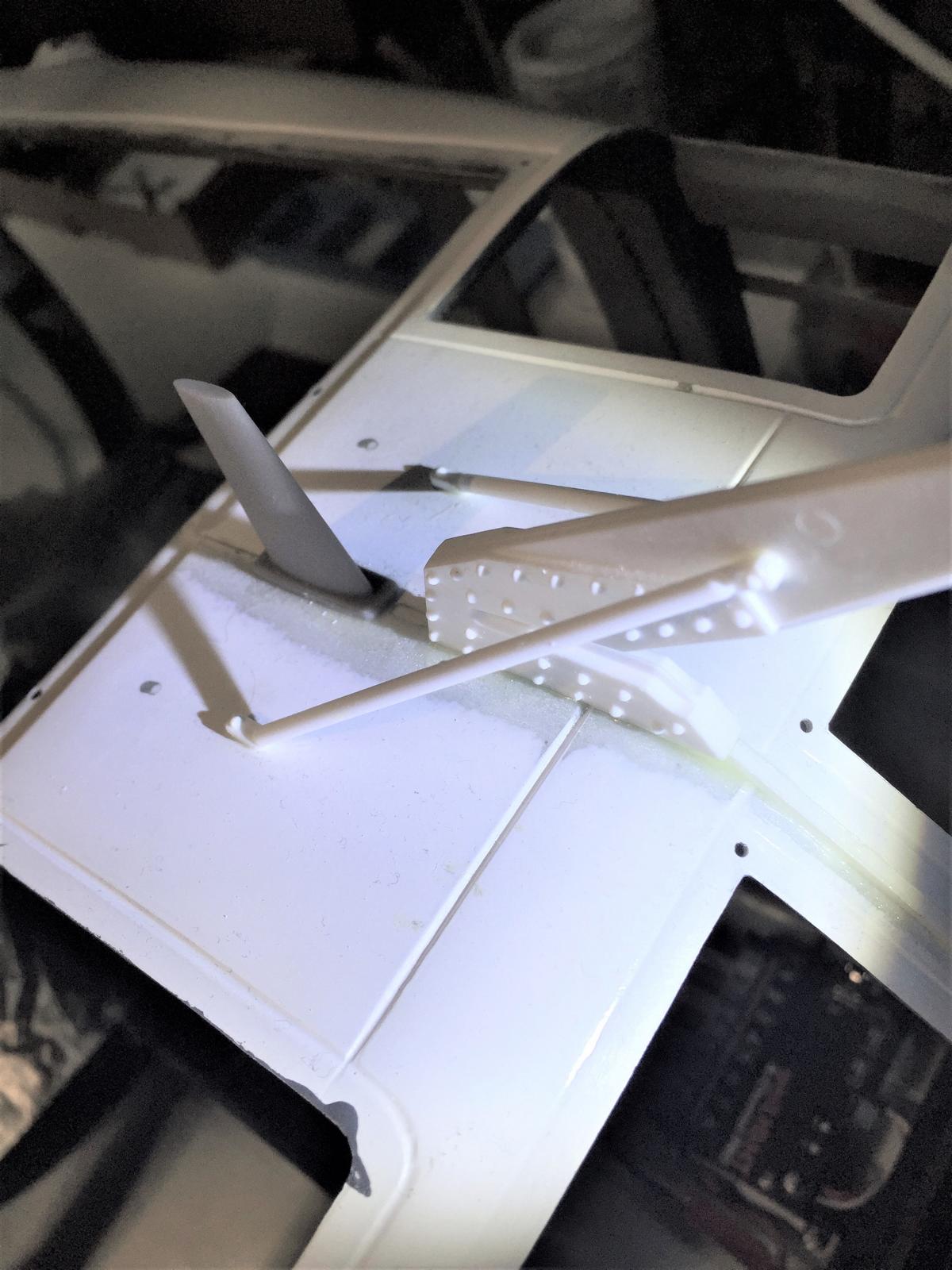
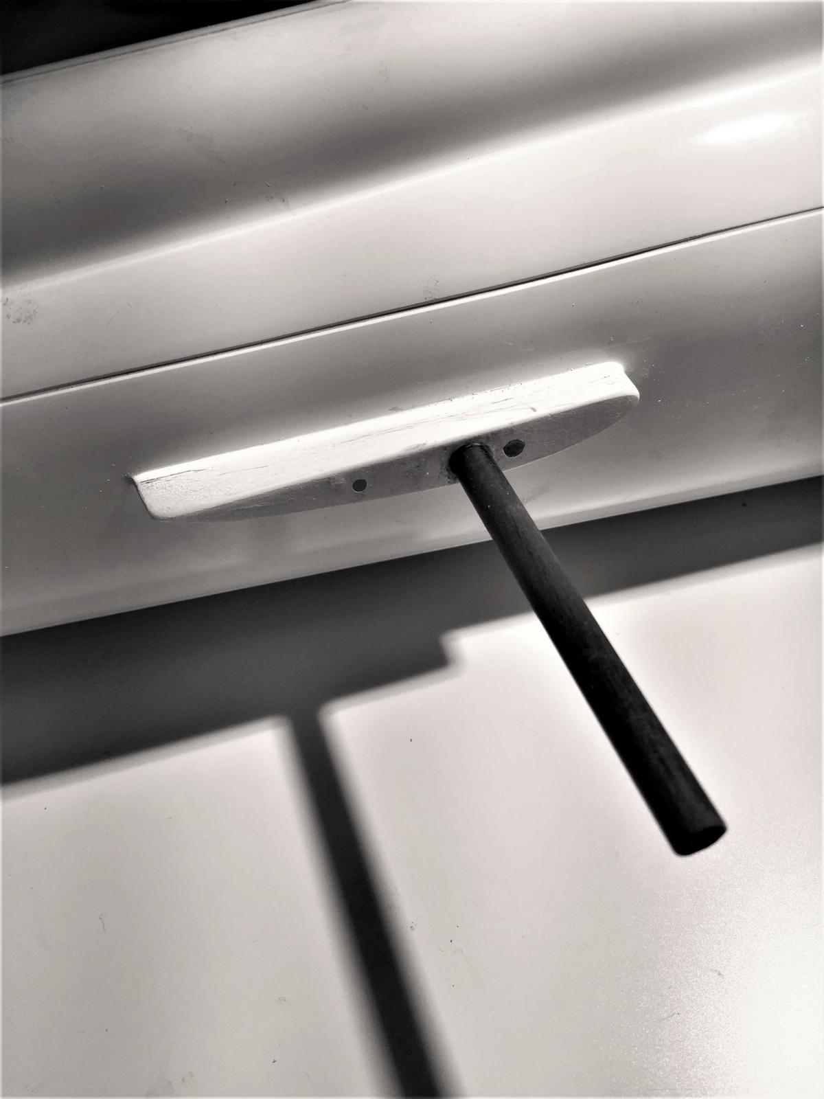
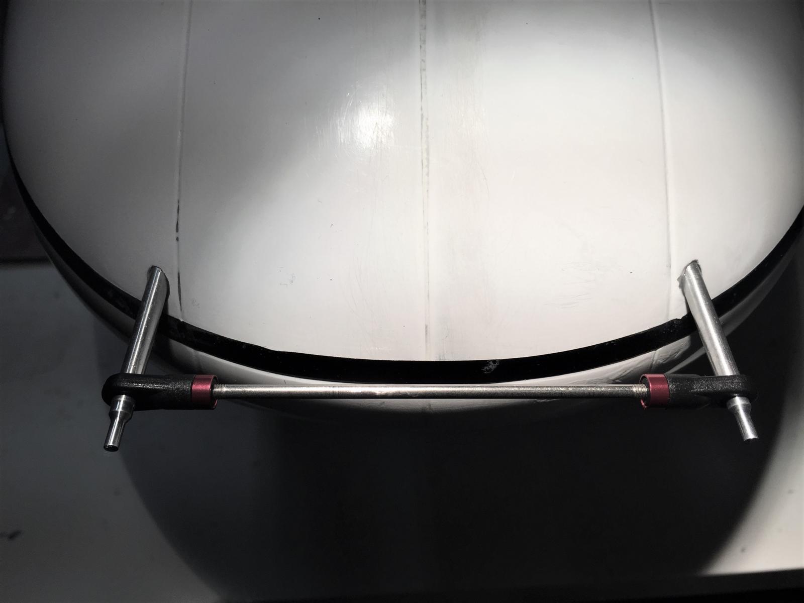
. - Pitot Tubes
Pitot tubes are glued with homemade tool that simply consists of a rod with it ends.
. - Doors and Hinges
The correct positioning of the doors is achieved by sliding a strip of thin cardboard all around the door.
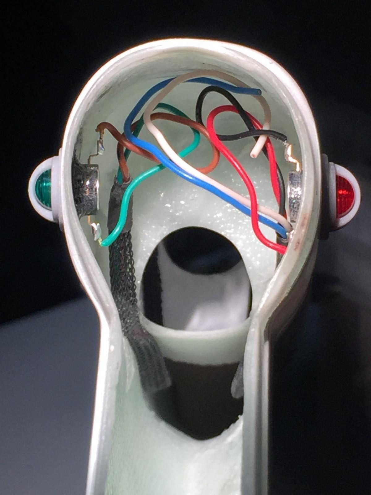
. - Tail Lights Wiring 1
Details of the electrical setup. For fewer cables, a trick is to share the negative wire with several lamps.
. - Tail Lights Wiring 2
The wires have logical colors and the white one is for the beacon located on the back of the tail.
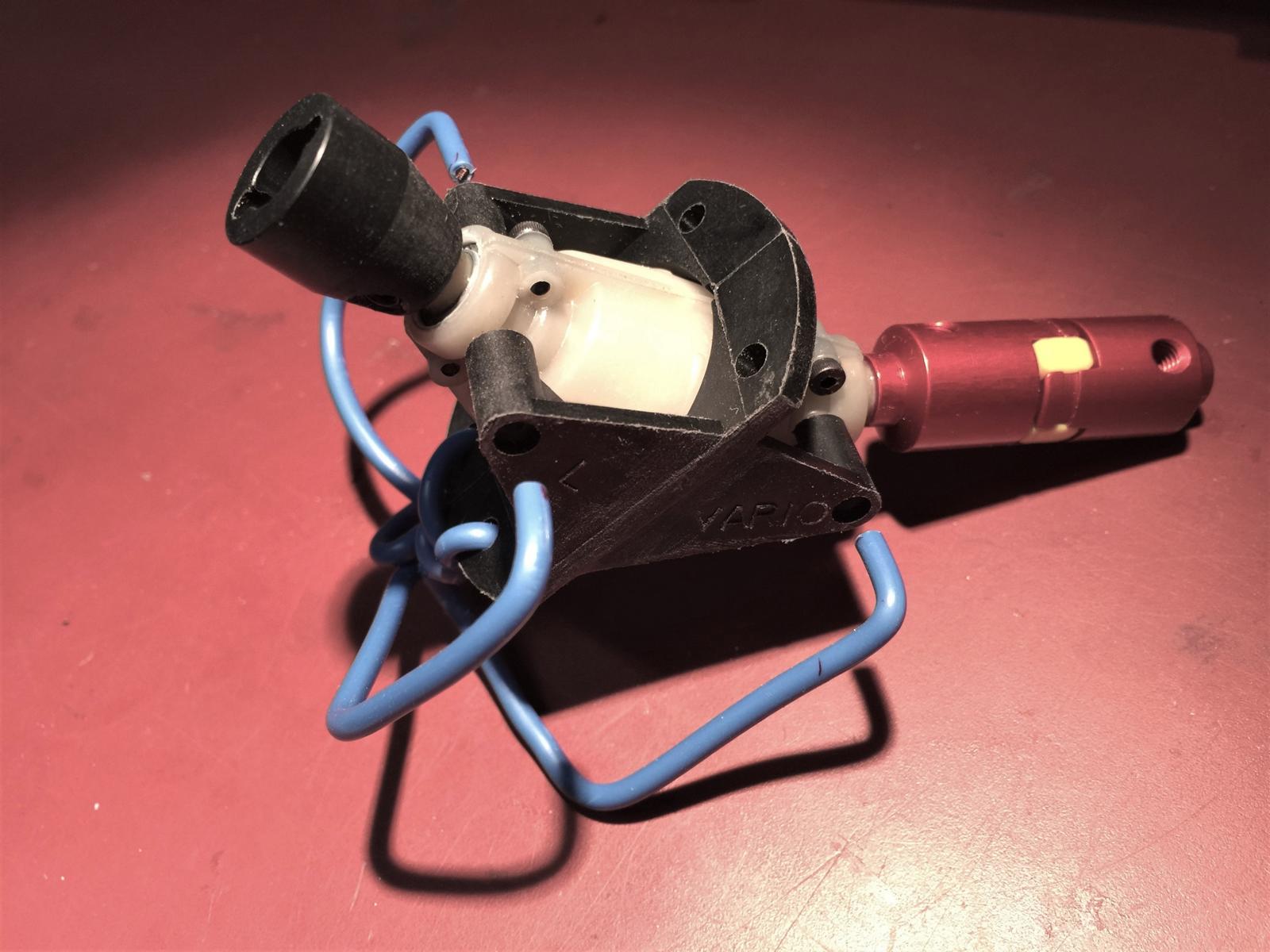
. - Gearbox
Homemade tool creation of a “spider” made from copper wire allowing to determine the location of the screws for the 40° gear box.
. - Gearbox Holes Marking
The legs of the “spider” are showing exactly where the holes must be drilled to install the 40° gear box.
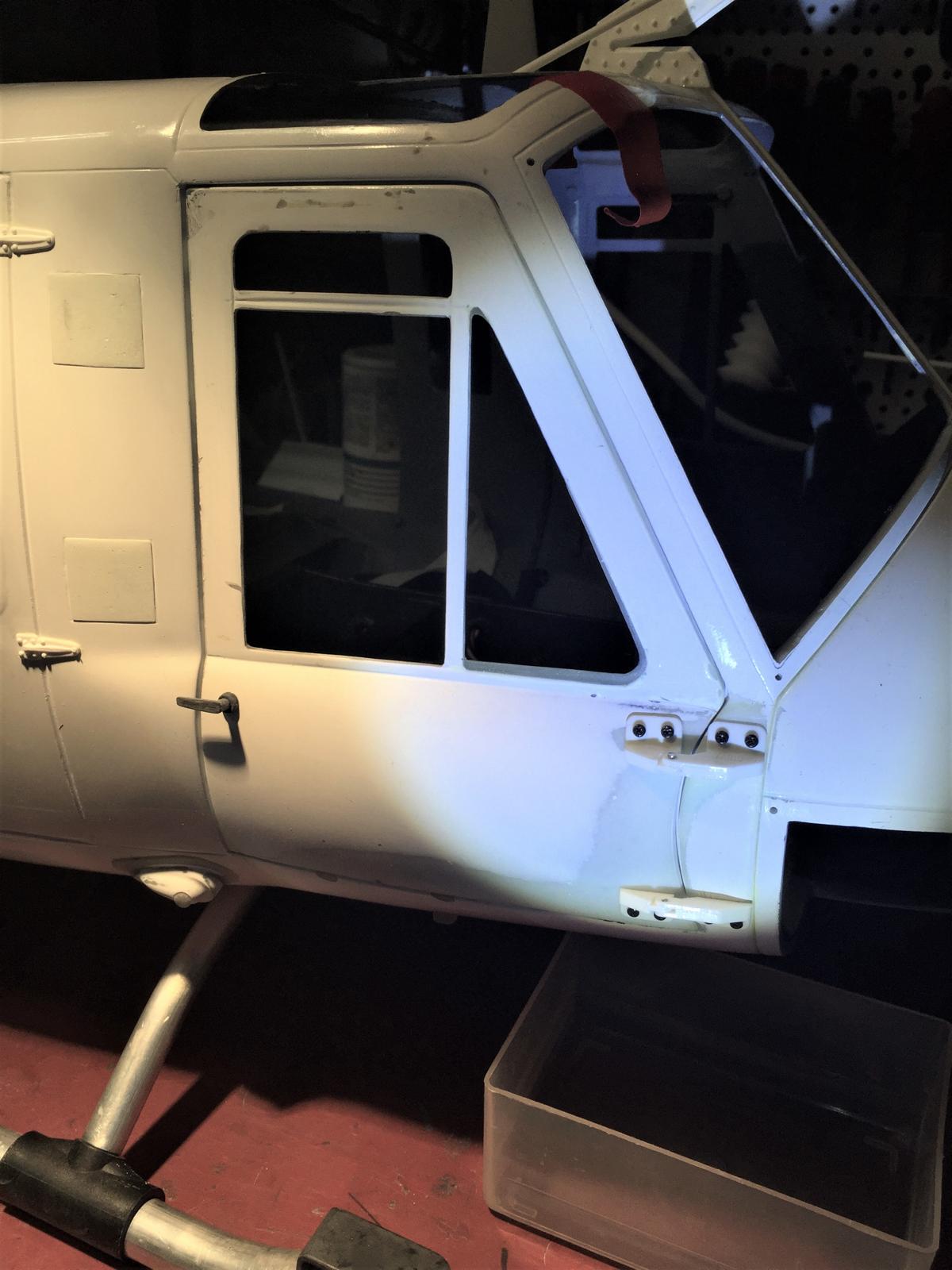
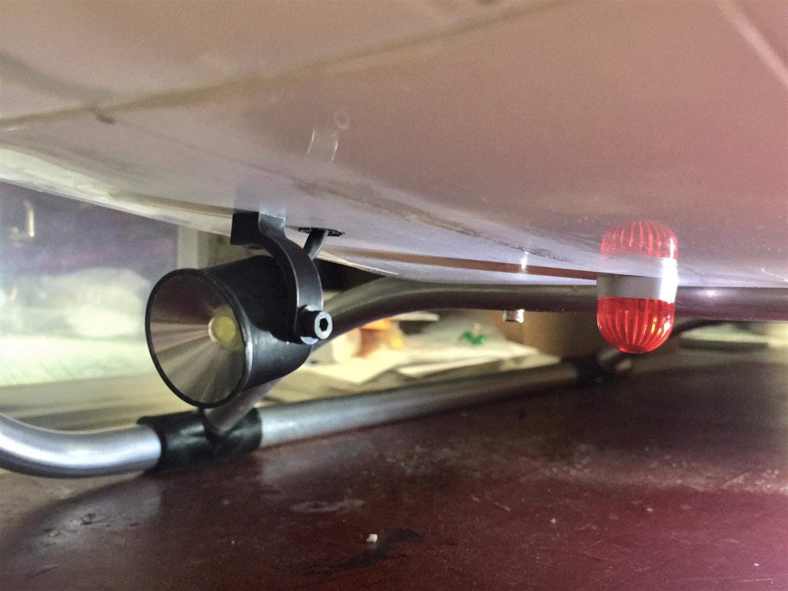
. - Front Lights
Installation of Spot and Rotating lights. The spot one is useful to see if far helicopter is facing the pilot, even in daylight.
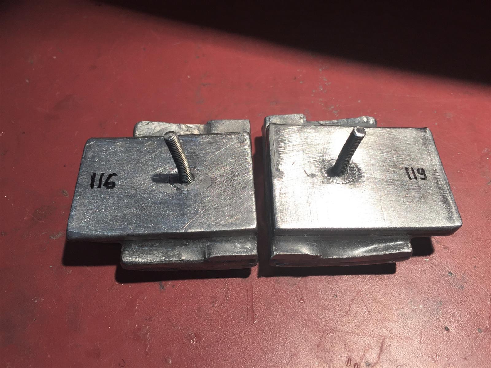
. - Weight Pods
Creation of Weight Pods glued in the nose of the helicopter. They are modular so more weight can be added afterwards, if needed.
. - Weight Pods Installation
Maintenance is easy as we just need to remove the bottom front window to access it.
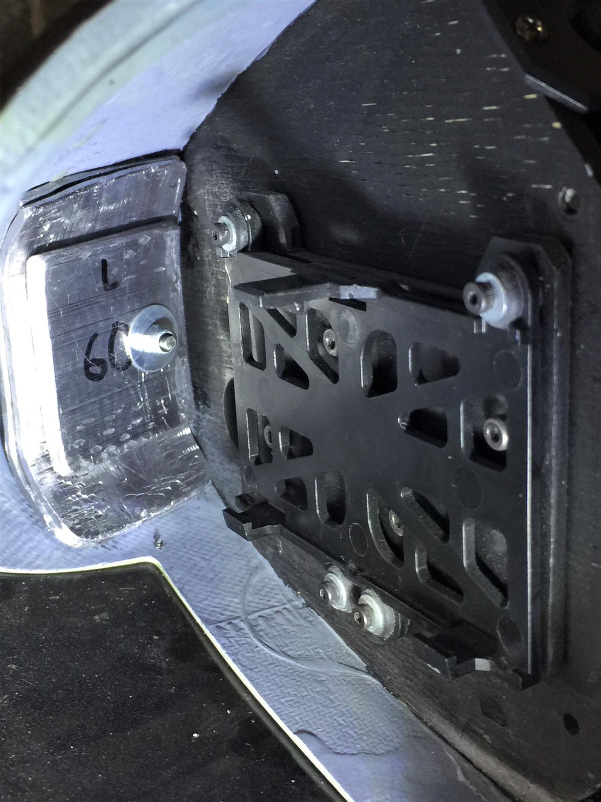
. - Batteries Installation
The central part receives a support for the battery of the turbine made with two plastic corners from a DIY store plus a Velcro ribbon.
. - Light Control Unit
The Light Control Module is installed under the floor, in which all electrical wires for the lights are converging.
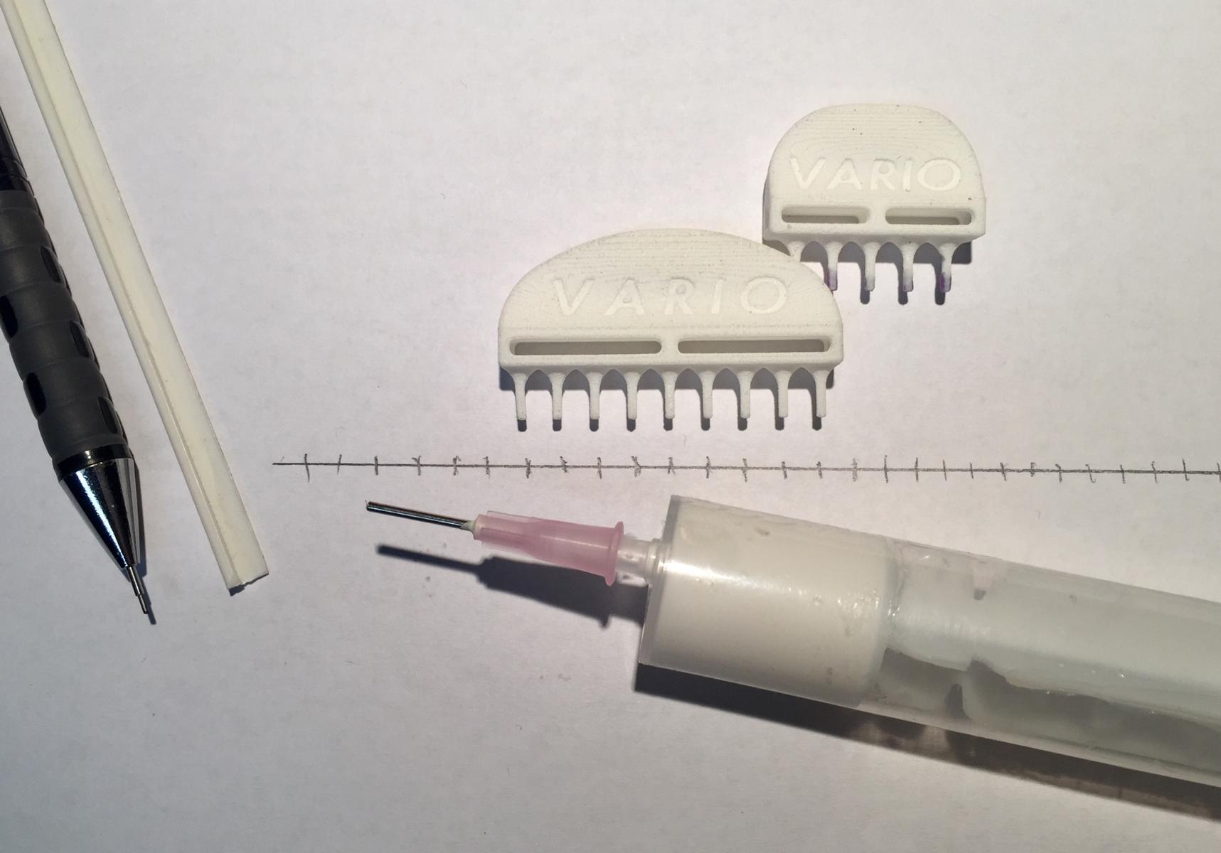
. - Riveting 1
Vario rivet combs are not used here to add rivet drops to the fuselage but to mark their location. Rivets are added with a 1.2mm needle syringe with glue Uhu Holzleim Original mixed with 15% of micro-balls.
. - Riveting 2
About 2’000 rivets were added. They got three different sizes depending their purpose on the real helicopter. The alignment of the rivets is not very regular on purpose, in accordance with the generation of this helicopter.
. - Primer Coat 1
Application of the primer by a professional automotive painter.
. - Primer Coat 2
Once the primer is complete, the fuselage is completely sanded with 1000 grain size wet abrasive.
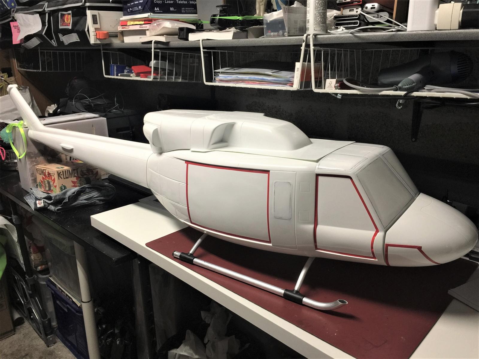
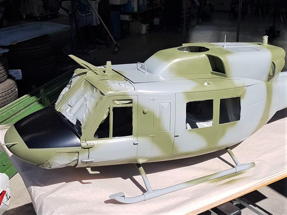
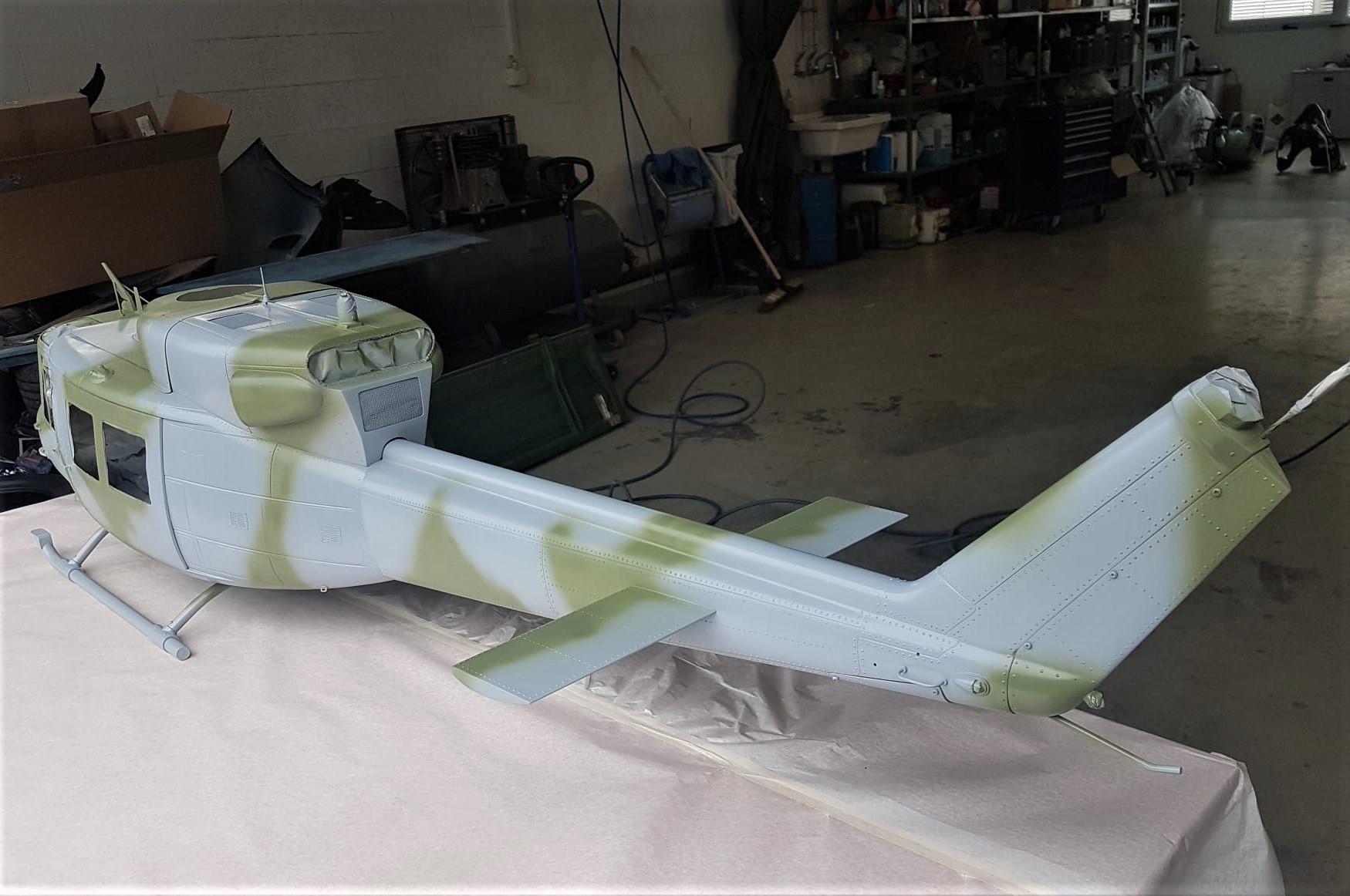
. - Camo Paint Job 1
Camo paint accordingly to the original Bell 212 AB ICO Aeronautica militare (Gruppo Tigre).
. - Camo Paint Job 2
For now looks like a “toy” until work is done to make it more realistic with adding dirty and patina.
. - Gluing Windows
Gluing windows with Uhu Max Repair transparent. The balsa stick is handy as easy to cut at the right lenght and put it in whatever position.
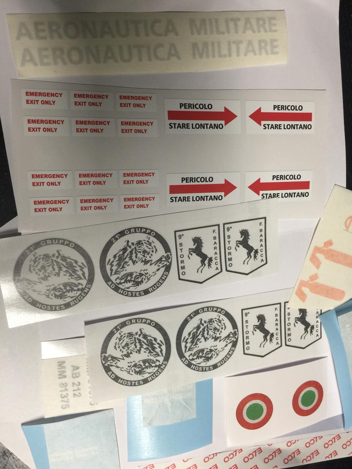
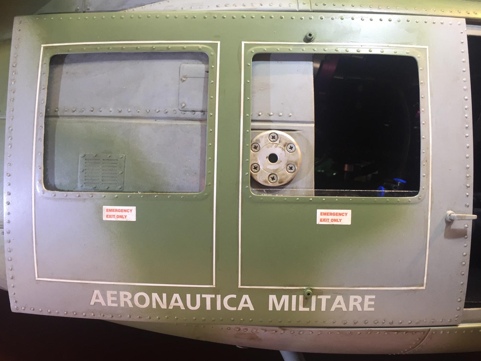
. - Homemade Stickers
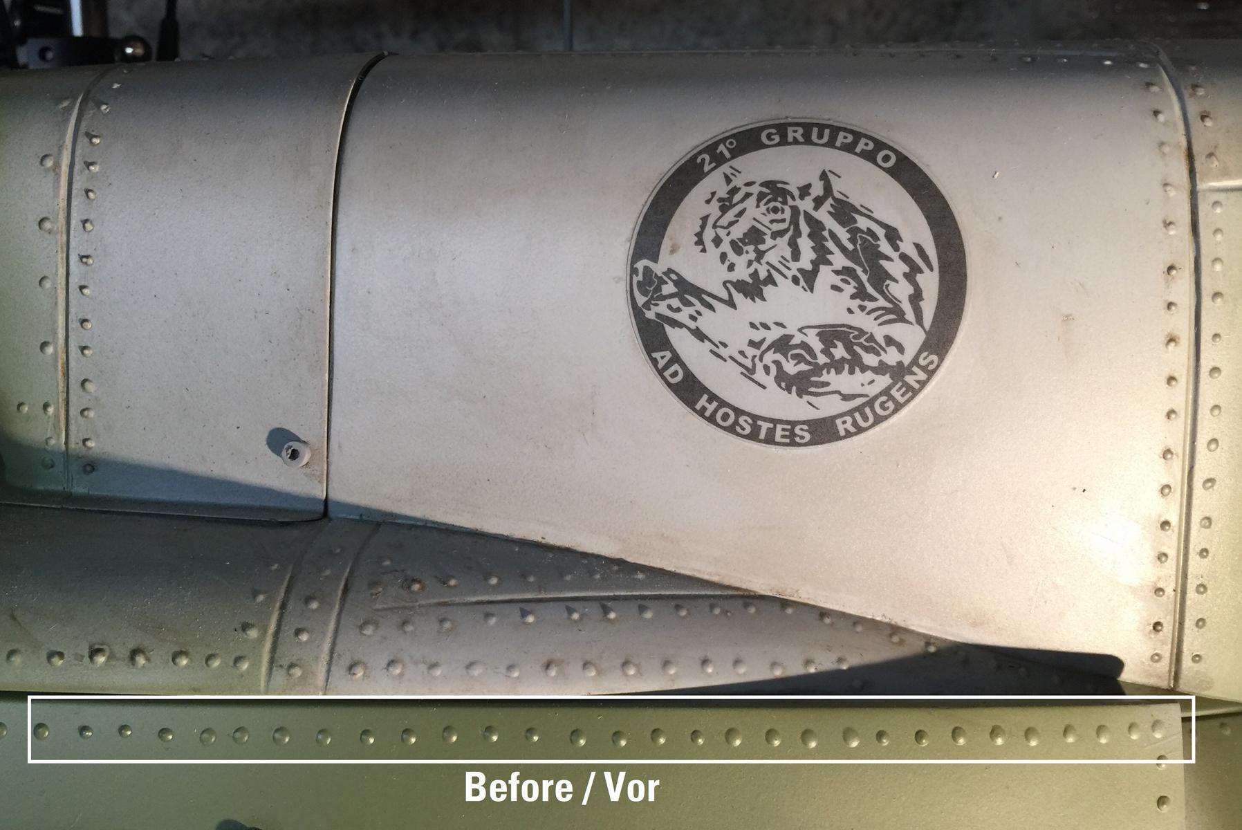
All homemade stikers, some based on images found on the internet but everything has been created and redesigned by hand. Printed by a professional who also weathered the colors for a more realistic rendering, see per example the orange tint of the fire extinguisher logo.
. - Paint Ageing 1
The helicopter is weathered after the stickers are placed and a matte finish varnish applied by the painter. The picture shows the difference without/with.
. - Paint Ageing 2
A tube paste called “Patine” is bought in a store that sells paint for Hobby. It is diluted according to the desired effect and applied with a cloth which is soiled beforehand.
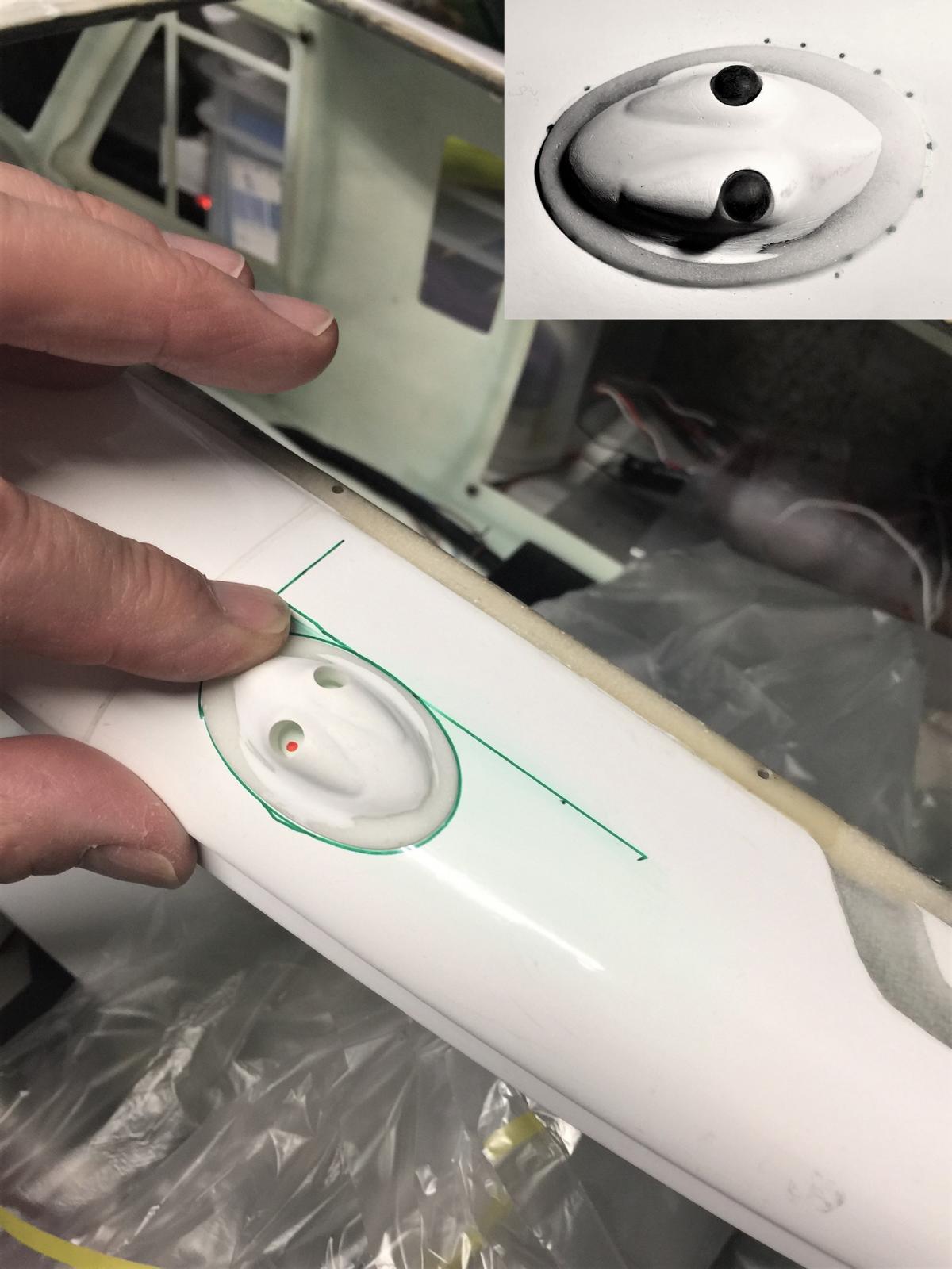
. - Paint Ageing 3
The missing dirt around the kerosene filling shows the difference.
. - Paint Ageing 4
The green area at the bottom looks really as a “toy” as not yet weathered.
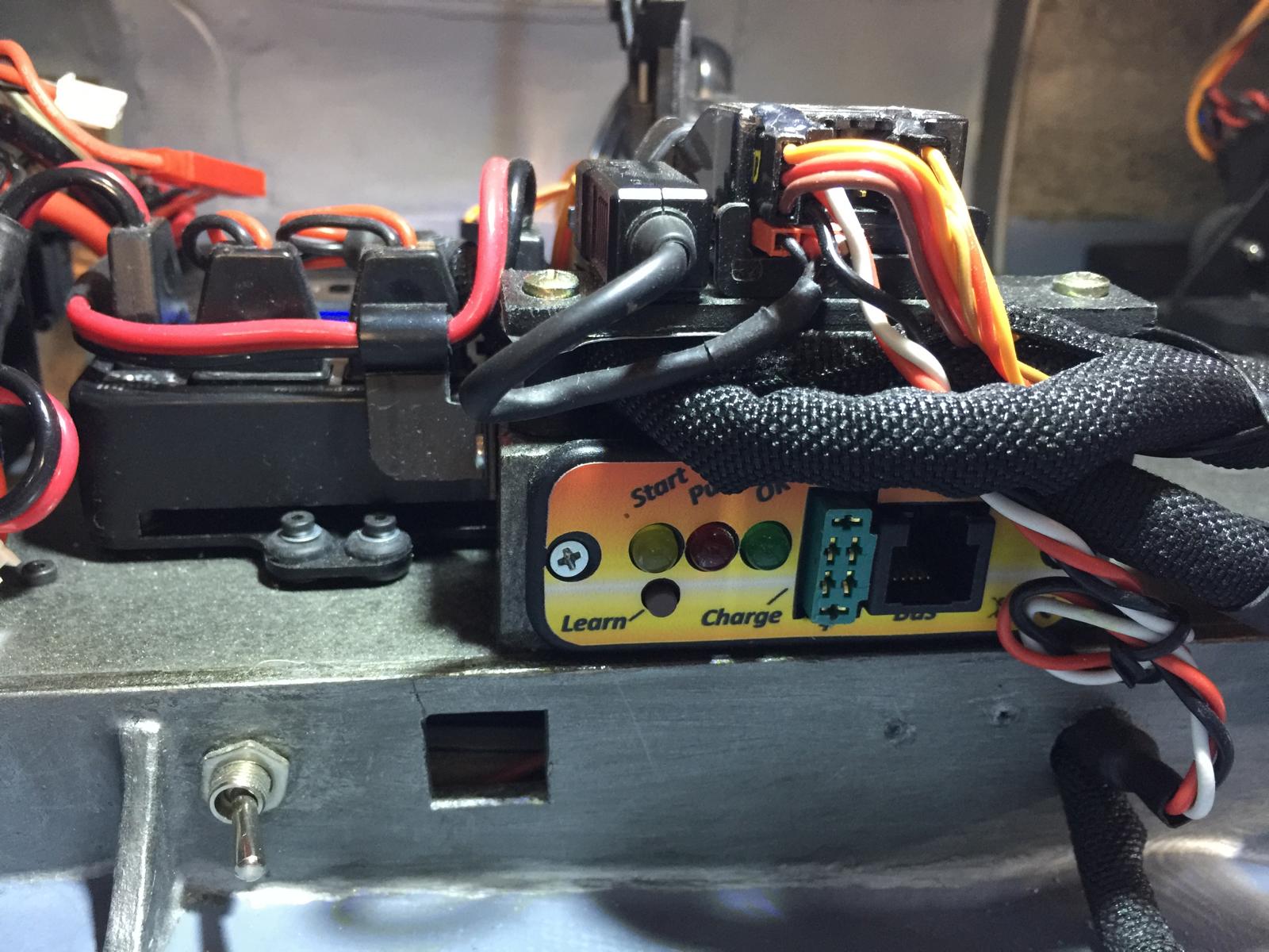
. - Electronic Setup 1
Interior is not scale but functional, here showing the switch of the PowerBox.
. - Electronic Setup 2
The switch located at the bottom is to cut off the battery powering the Light Control Module hidding under the floor. The square hole allows to connect a USB cable to program same module.
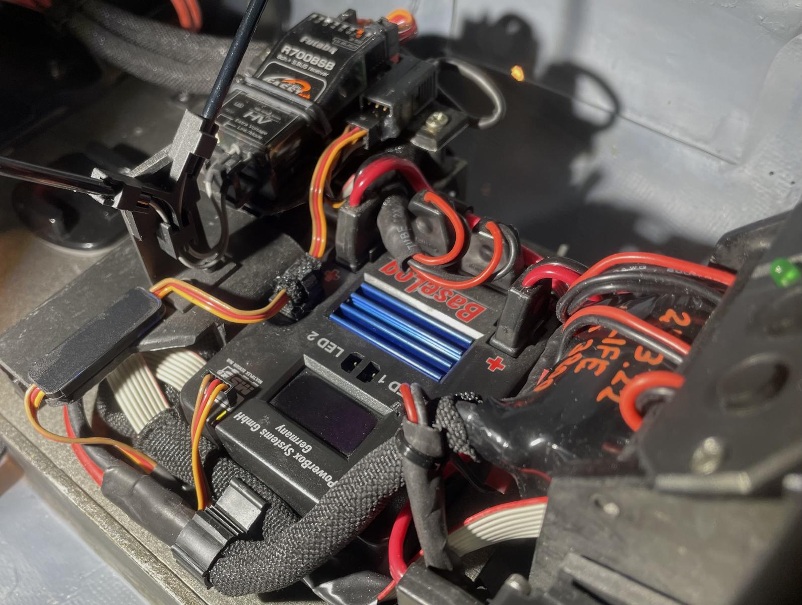
. - Electronic Setup 3
A clean setup of the components is recommended to avoid longer cables and overlaps.
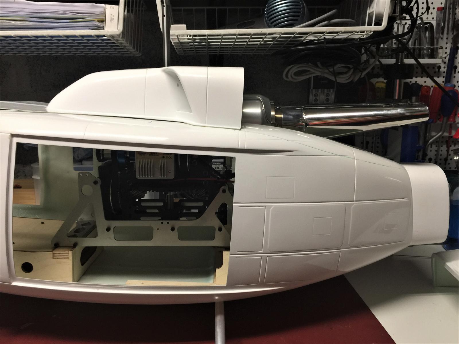
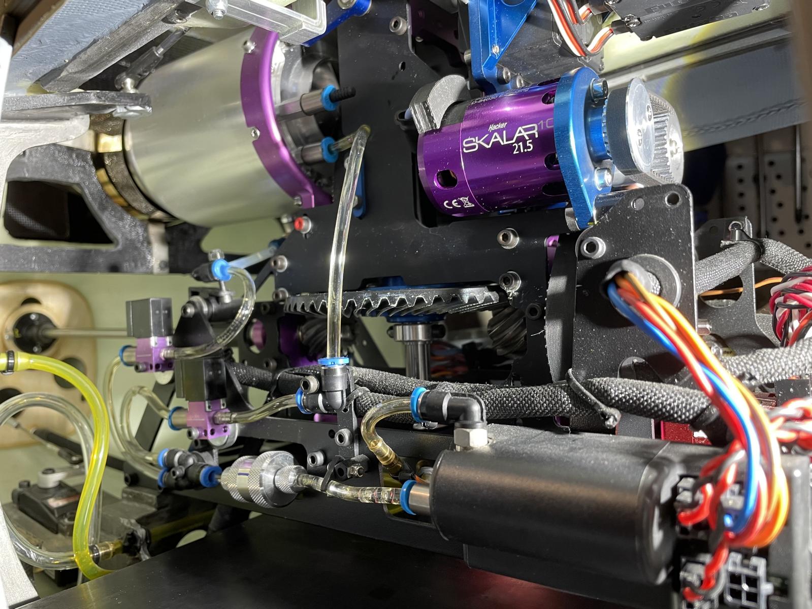
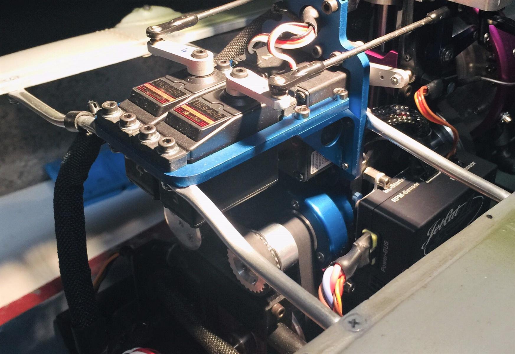
. - Turbine Setup
A clean setup of the components does contribute to a safe operation of the turbine, reliability and easy access for maintenance.
. - Fuselage Rigidity Improvement
It is recommended to add wood work to the front of the helicopter to stiffen the front of the fuselage.
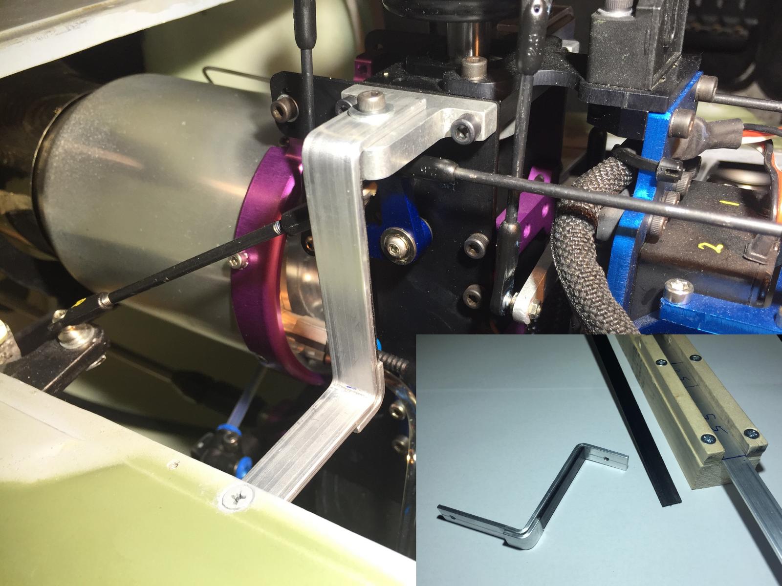
. - Mechanic Rigidity Improvement 1
Small hand made alu tubes are mounted to prevent oscillations potentially occurring at the top of the mechanics. Their shape is very important as they are very close from the engine hood.
. - Mechanic Rigidity Improvement 2
Flat carbon-reinforced aluminum rods are created with a homemade tool. Their particular shape is required as they are very close from the engine hood.
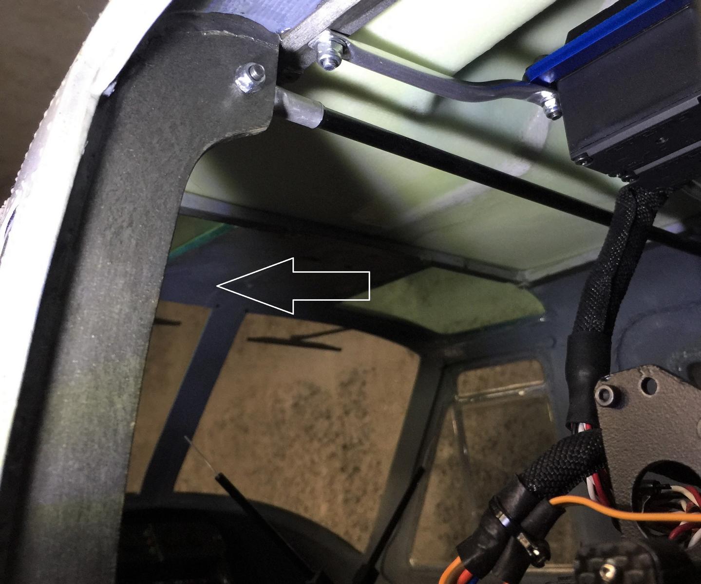
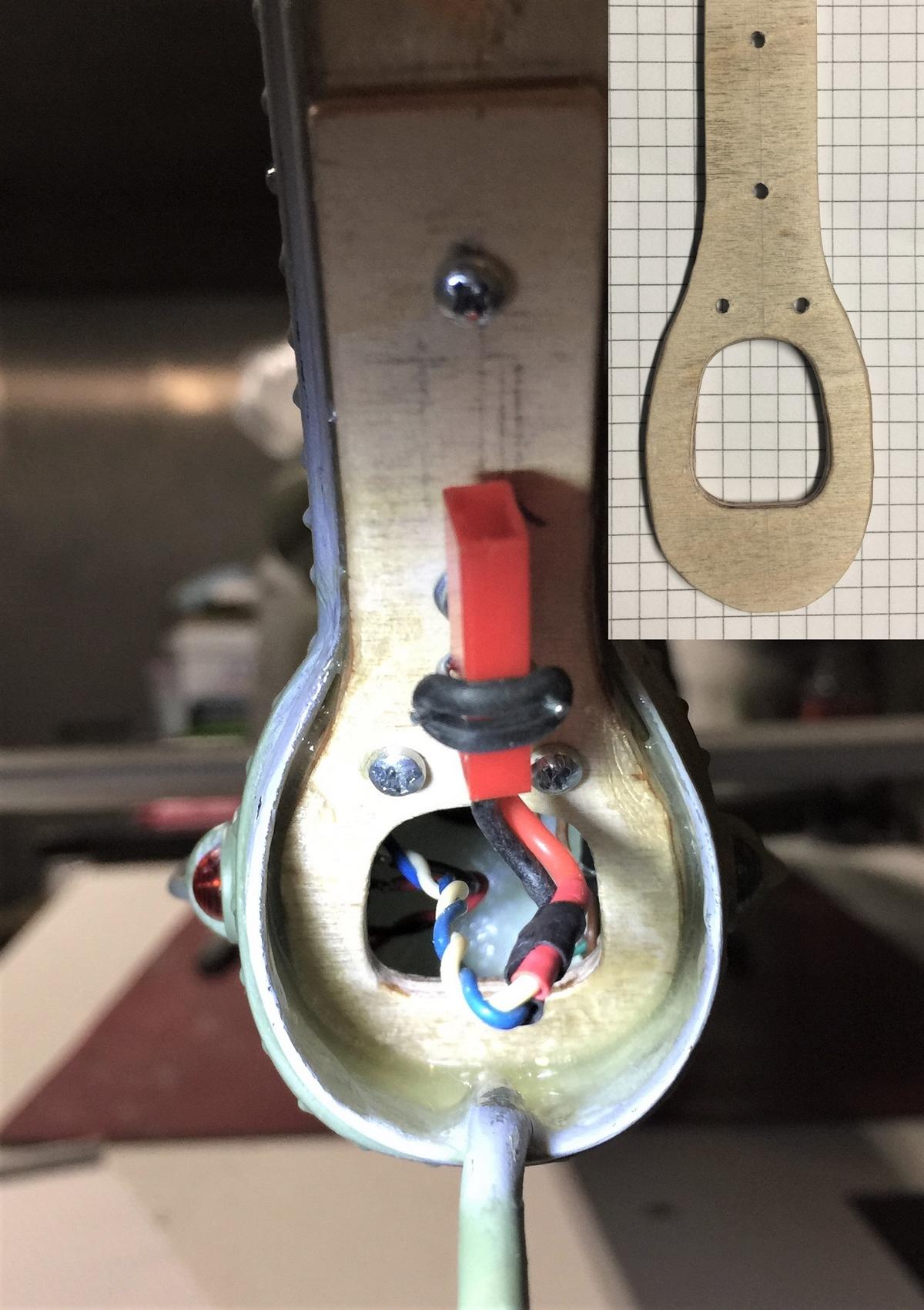
. - Tail Rigidity Improvement
A piece of plywood is added to vertically stiffen the tail. A small window is then necessary for the maintenance.
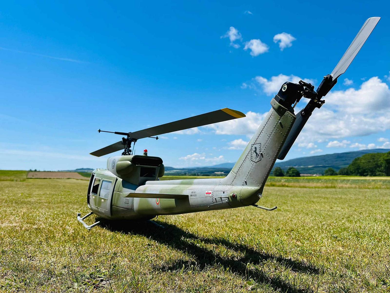
. - Static Presentation
The helicopter is ready to fly although the tail blades do not yet have same color as the main blades. Also, their end is not yet yellow but it is detail.
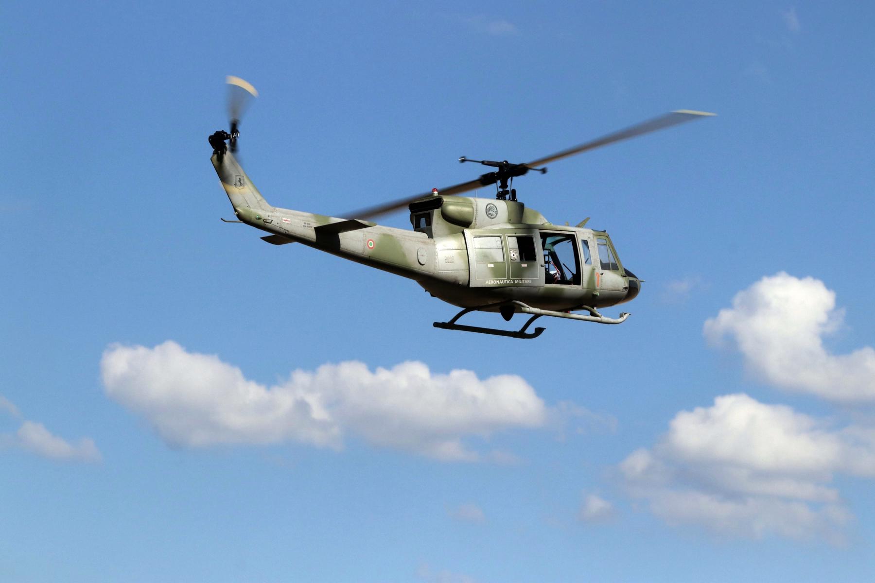
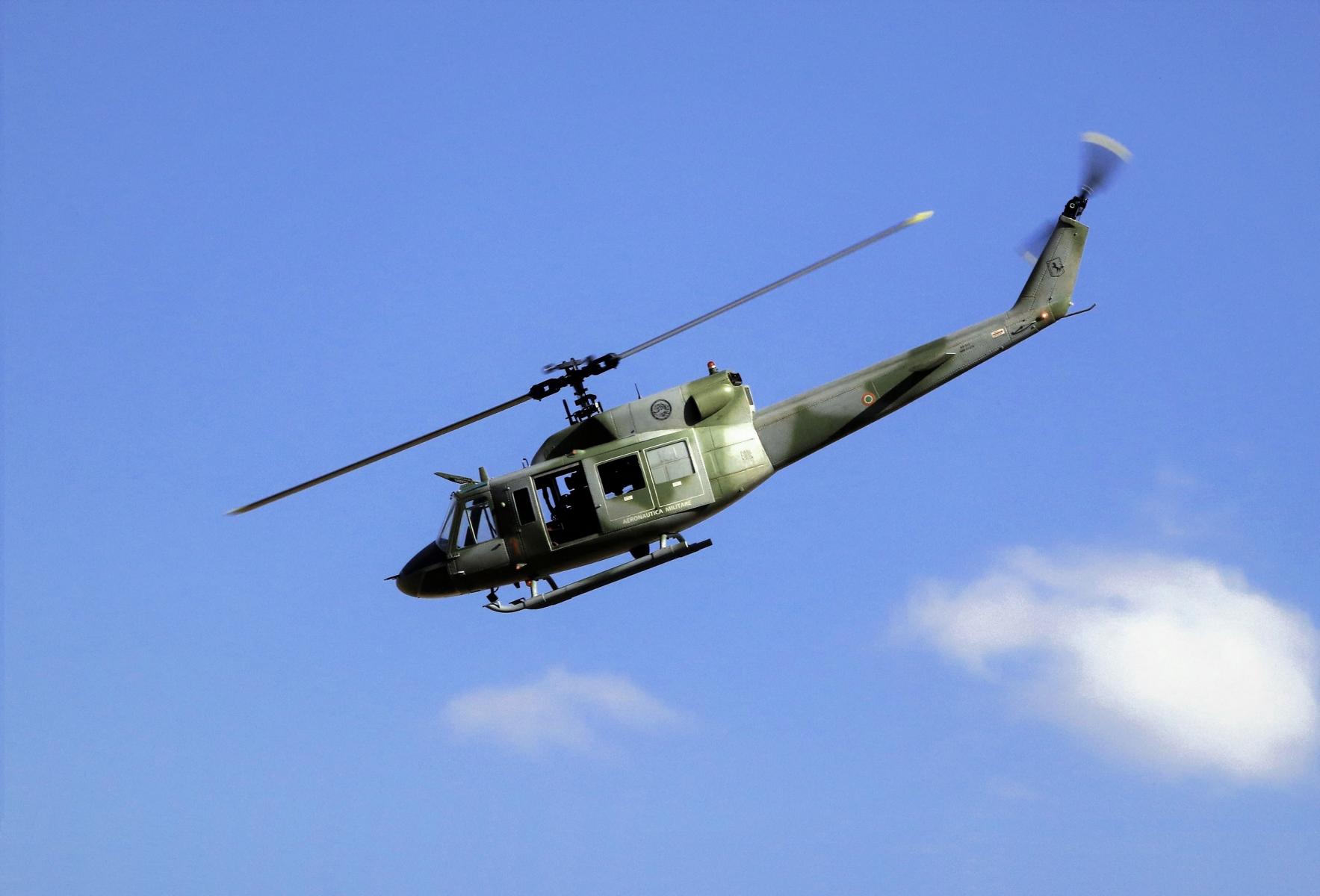
. - Go Fly 1
The aspect in flight is realistic but it still lacks the pilot!
. - Go Fly 2
From now on the left door will remain closed as the turbine get enough air (the other door remains open).